1 Application range
This relay is used in generators, transformers and circuits to reflect the negative sequence component of an asymmetric short circuit as a voltage blocking element.
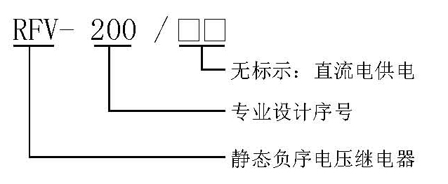
2 Model definition
3 Working principle and main performance
3.1 Working principle
After the AC voltage UBC is converted by AC, it is phase-shifted and added to the converted AC voltage UAB; then the harmonics other than 50HZ are filtered through the 50HZ bandpass; then the DC voltage is rectified and filtered and sent to the setting circuit. The setting circuit changes the setting value by changing the magnification of the operational amplifier; the output voltage UZ of the setting circuit is sent to the level detector and compared with the comparison voltage UB; the output of the drive relay acts.
Under normal operating conditions, the negative sequence component is close to 0, UZ<UB, and relay J does not act; when an asymmetric short-circuit fault occurs and the negative sequence component is equal to or greater than the set value, UZ≥UB, relay J acts.
3.2 Main performance
3.2.1 This relay is mainly composed of integrated circuits. Stable performance, high reliability, high accuracy of the action value, small discrete value, wide setting range, fast action and return speed, good return coefficient, small load on the transformer, vibration resistance, anti-interference and high insulation level.
3.2.2 The setting is set by the dial switch on the relay panel, which is intuitive and convenient. The relay debugging is simple and convenient, without adjustment on site.
3.2.3 During normal operation, the negative sequence imbalance component is extremely small.
3.2.4 The relay has running and action indicator lights.
4 Technical conditions
4.1 Environmental reference conditions
Environment temperature: 20±2℃
Relative humidity: 45%~75%
Atmospheric pressure: 86~106KPa
4.2 Normal use conditions
Ambient temperature: -10℃~+50℃
Relative humidity of environment: not more than 90%
Atmospheric pressure: 80~110KPa
Limit temperature during storage and transportation: -25℃~+70℃
The altitude of the place of use: no more than 2500 meters
The surrounding medium of the operating environment has no explosion hazard; it does not contain corrosive gas; the concentration of conductive dust contained should not reduce the insulation level
Below the allowable limit value.
Reliable power supply.
4.3 Rated parameters
Rated AC voltage: 100V
Rated frequency: 50HZ
Auxiliary DC power supply rated voltage: 220V, 110V; allowable voltage fluctuation range: 0.8 to 1.15 times the rated voltage.
4.4 Characteristic parameters
Action range: 2~21.8V, level difference: 0.2V
Setting value error: not more than ±4%, the action value deterioration under various short-circuit conditions: not more than ±4%
Action time: no more than 30Ms, return time: no more than 30mS
Return coefficient: not less than 0.9
4.5 Maximum power consumption:
AC voltage circuit: under 100V, each phase is not more than 0.5VA.
Auxiliary power circuit: under the condition of rated voltage 220VDC, not more than 6W.
4.6 Maximum capacity of contacts:
Cut-off load capacity: DC 250V or less, τ=5ms, inductive load 50W, resistive load 150W;
AC below 250V, load 1200VA;
Allow long-term connection current: 5A.
4.7 AC voltage circuit overload capacity: continuous work under 1.2 times the rated voltage
4.8 Insulation resistance: Use an open-circuit voltage 500V megger to measure the insulation resistance between the exposed non-charged metal parts or shells of the relays connected to each conductive terminal and should not be less than 10MΩ.
4.9 Insulation withstand voltage: each lead-out terminal to the housing locking screw can withstand a power frequency voltage of 2000V, and the same group of contacts can withstand a power frequency voltage of 1000V, which lasts for one minute without breakdown.
4.10 Anti-interference performance: meet the national GB6162-85 "Electrical Interference Test of Static Relays and Protection Devices" standard.
4.11 Electrical life: In the DC250V circuit, cut off the current τ=5ms, 50W, more than 104 times.
4.12 Mechanical life: The contact is 3 million times in no-load state.
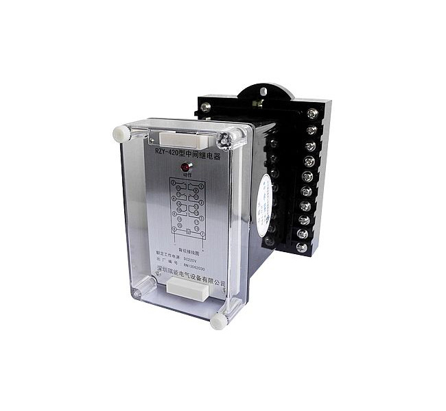
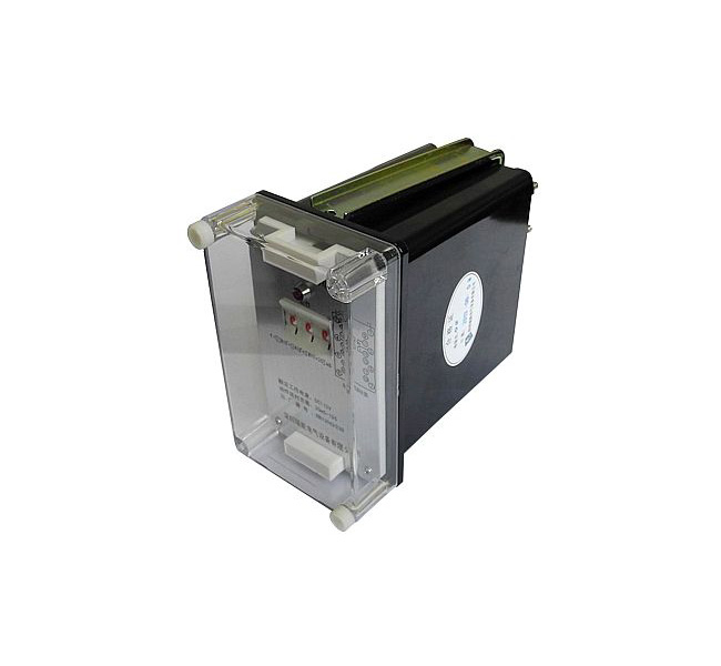
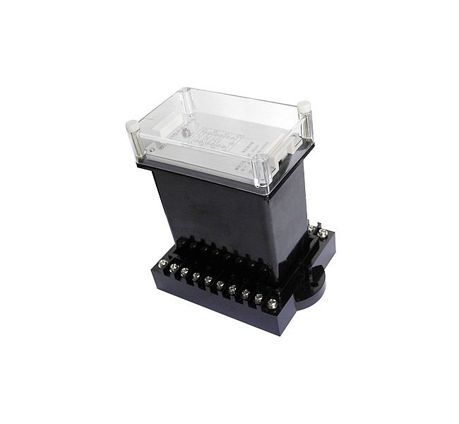
5 Structure type (see the relay structure size diagram for details)
5.1 The rear wiring structure of the embedded board AK11 and the rear-view wiring diagram of the protruding board front wiring AQ11 (subject to company product samples)
6 Use
6.1 Before energizing the relay, confirm whether the voltage level and current value of the connected relay are consistent with the actual parameters, otherwise the relay may be damaged; check whether the relay is damaged during transportation and storage, and the relay screw fasteners should not be loose; There are damaged parts, please contact us to replace them.
6.3 According to the formula on the panel of the relay, use the dial switch to set the value.
Negative sequence component setting range: 2~21.8V, setting formula: U=2[□+0.1□+1]V
7 Ordering instructions
Please specify the relay model, specification, quantity, structure, auxiliary power supply rated voltage, AC rated voltage, setting range and other requirements when ordering.

 Language