1 overview
This device is used to eliminate any type of ferromagnetic resonance in the large current system (110kV-220kV substation is taken as an example in this manual) which is directly grounding the neutral point. It can be widely used in the high-voltage substation of electric power, petroleum, metallurgy, mining, steel and other industries.
There are many reasons for high voltage system resonance. For example: when the circuit breaker with fracture capacitor was carried out on the empty bus with PT break-brake operations, the transient operation is often in equalizing capacitor between PT and stimulate the ferromagnetic resonance phenomenon, the phenomenon in 110 kv, 220 kv substation occur frequently, and the duration is long, sometimes can maintain long-term since, thus may cause electromagnetic voltage transformer over-excitation burning, explosion, accident cause consequences even more serious system; Moreover, ferroresonance caused by system faults and PT burnout and explosion accidents also occur frequently.
So far, the technical measures to eliminate the resonance of 6kV -- 66kV neutral insulated power grid (small current system) have been relatively mature, but the technical measures to eliminate the resonance of 110kV -- 220kV substation have not made a breakthrough in a long time.
The MGS-3/4 type microcomputer harmonic elimination device developed and produced by our company has successfully solved these problems. The STM32F103 microcontroller and solid state relay are the core components of the device. The STM32F103 single chip microcomputer realizes the identification of all kinds of ferroresonance overvoltage and the effective control of the solid state relay under the support of the peripheral circuit. The solid state relay is controlled by the STM32F103 single chip microcomputer and performs the task of damping and detuning. The device uses LCD screen, signal indicator light, printer, button and so on as man-machine interface, the operation is simple, intuitive and accurate.
2Characteristics and technical specifications
2.1 the characteristics of
2.1.1 There is no need for setting and debugging, and the maintenance is small.
2.1.2 Automatically display and record the occurrence time and relevant parameters (amplitude and frequency) of overvoltage and ferroresonance.
2.1.3 Overvoltage and ferroresonance can be distinguished.
2.1.4 Comprehensive alarm signal can be provided, which can automatically display or record the time of fault occurrence and relevant parameters.
2.1.5 Suitable for 110kV ~ 220kV voltage grade of various characteristic resonant frequencies (1/3 frequency division, 1/2 frequency division, power frequency, triple frequency), wide application range.
2.1.6 Accurate diagnosis, rapid and thorough elimination of harmonic.
2.1.7 It can store twenty times of fault information, recall and display it.
2.1.8 With RS-232 or RS-485 communication function, the communication protocol is CDT and Modbus protocol.
2.1.9 There are three alarm node signal outputs, which can distinguish resonance, overvoltage and power loss.
2.2 Technical specifications
2.2.1 Working power supply: AC/DC 110V~ 220V (-20% ~ +10%); The power consumption of 15 w or less.
2.2.2 Ambient temperature: -10℃ ~ +55℃.
2.2.3 Relative humidity: less than 90%.
2.2.4 Resonant frequency application: 1/3 frequency 1/2 frequency power frequency triple frequency
2.2.5 Contact capacity of alarm relay: AC 250V 8A; 30 v DC 2 a.
2.3 Model and version
2.3.1 Model meaning
MGS Microcomputer power resonance diagnosis and elimination device
2.3.2 Version meaning
MGS-3 It is suitable for 110kV system
MGS-4 Suitable for 220kV system
2.4Comparison table of model and function
|
Model
|
Dimensions (W × H × D)
|
Application
|
|
MGS-3
|
150X210X220 mm
|
110kV system
|
|
MGS-4
|
150X210X220 mm
|
220kV system
|
3. Main differences with similar devices
3.1 The device has strong anti-interference ability and high data acquisition accuracy.
3.2 The central processor of the device adopts high-performance 32-bit monolithic microcomputer, which has fast operation speed and strong control ability; Overvoltage and ferroresonance can be distinguished.
3.3 The device can automatically display and record various failure times and relevant parameters to provide data for field analysis.
3.4 The device can store twenty times of fault information, and can be recalled for display.
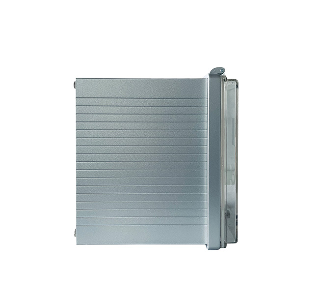
3.5 The device adopts plug-in structure, simple and convenient maintenance.
3.6 The device adopts large screen LCD display of Chinese characters, and the stored information will not be lost after the device is powered down.
4 Principle of device
The device takes STM32 series microprocessor as the core, and is composed of AC sampling, solid-state relay, signal light group, LCD Chinese display screen, keys, serial port output signal (RS232 or RS485 interface), alarm output signal and other parts.
After the device is energized and initialized, the frequency and amplitude of the open triangle voltage signal and the auxiliary detection circuit signal are detected in real time. When it is detected that the voltage signal of the zero-sequence circuit is a continuous fundamental frequency with high amplitude, it is determined as the fundamental frequency zero-sequence resonance. When it is detected that the voltage signal of the zero-sequence loop is continuous 1/3 frequency division, 1/2 frequency division or 3 high frequency with high amplitude, it is determined to be the zero-sequence resonance of the frequency division. At this time, the device sends out a trigger pulse to turn on the solid-state relay 1 and open the detuning circuit, so that the zero-sequence resonance will disappear quickly under the strong damping. When the device detects that the voltage signal of the positive sequence circuit is continuous and high amplitude fundamental frequency, it is determined as the positive sequence resonance of the fundamental frequency. When it is detected that the voltage signal of the positive sequence loop is continuous 1/3 frequency division, 1/2 frequency division or 3 high frequency frequency with high amplitude, it is determined as positive sequence resonance of the frequency division. At this time, the solid-state relay 2 turns on and turns on the detuning circuit, so that the positive sequence resonance will disappear quickly under strong damping. When the device cancels the resonance of the corresponding property, the resonance signal always exists, then the device is judged to be overvoltage.
In the above process, the LCD display displays the corresponding fault information, and the signal indicator light group indicates the corresponding fault information. If it communicates with the upper computer, the communication interface sends the corresponding fault information to the upper computer.
After the fault is eliminated, the device will automatically return to the initial state and start real-time detection again. Thereafter, if the system resonates again, the device starts again to eliminate.
5. Composition of device software
The device software is mainly composed of sampling program, data processing program, fault processing program, display program and so on. This is shown in Figure 5-1.
6 Hardware composition of the device
The hardware of the device consists of the following components:
6.1 the output board
Using module power supply, output DC+5V, DC+12V; Place high power harmonic elimination element, integrated alarm relay and signal conditioning circuit.
![HH8[T){`9LX]R1Q{BA@2LGT.png](/Data/szruineng/upload/image/20210114/6374623143075139032155784.png "HH8[T){`9LX]R1Q{BA@2LGT.png")
6.2 the main board
Adopt high performance 32 bit single chip microcomputer, fast operation speed, strong control ability, reliable operation, software parts watchdog to prevent the occurrence of crash.
6.3 display board
128×64 LCD and LED lights are used to display and indicate various information
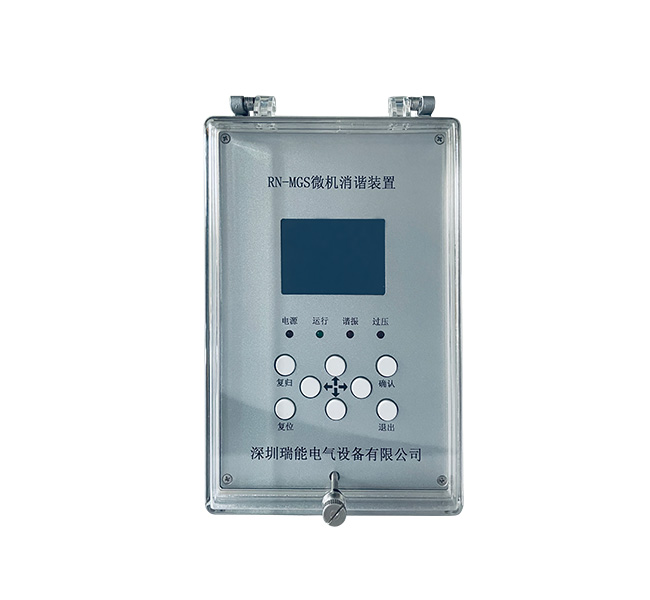
7. Instructions for the device
7.1 the keys
The front panel of the device adopts light touch button. The functions of the eight keys are defined as follows:
"Move up" key: move the cursor up or increase the data by 1;
"Move Down" key: move the cursor down or subtract 1 from the data;
"Move Left" key: Move the cursor left;
"Move right" key: move the cursor right;
"Exit" key: exit function;
"Confirm" button: select Confirm;
"Reset" key: restart the device;
"Return" key: manual return alarm signal (LED light and signal relay).
7.2 light
Indicator light is used to indicate the operating state of the device and fault information. The five signal indicator lights are defined as follows:
"Power supply" light: when the device is running, the "power supply" light turns red and flat;
"Operation" light: when the device is running, the "operation" light flashes green light;
"Resonant" lamp: when resonance occurs, "resonance" lamp red flat light;
"Overvoltage" lamp: when overvoltage occurs, the "overvoltage" lamp turns red and flat;
7.3 Operation Instructions
7.3.1 Contents of LCD display when starting up
When power-on, the LCD display device starts the screen and lights up the LCD background light (see Figure 7-1). The figure shows the device model, name and time in order.
3.png")
7.3.2 Run the main menu interface
After power-on, press "Confirm" or "Exit" to enter the LCD screen of the main menu (as shown in Figure 7-2). Under any interface, if you do not press the button, the device will automatically extinguish the screen in about 1 minute. When the screen is extinguished, press any key to light the backlight of the system.
![`19JZTC62)1I)JY5_UUJV]F.png](/Data/szruineng/upload/image/20210114/6374623188968109376386129.png "`19JZTC62)1I)JY5_UUJV]F.png")
Note: The shaded place in Figure 7-2 is the position of the cursor. Use "Move Up" and "Move Down" keys to change the position of the cursor and select the level 1 menu of different functions.
The following describes the functions and operation methods of each sub-menu of the main menu:
1) Real-time data
After the cursor moves to the first-level menu of "Real-time Data", press "OK" to enter the second-level menu under this menu. You can choose to view real-time data of zero sequence voltage or positive sequence voltage (see Figure 7-3). Select the corresponding voltage by "Up" and "Down" keys, and press "OK" button to display data. Press the "Exit" button to return to the top level menu.

2) Operating voltage
After the cursor moves to the menu of "Action Voltage", press "OK" to enter the sub-menu (as shown in Fig. 7-4) to view the action value of voltage of each frequency. At the end of viewing, press "Exit" to return to the main menu of the previous level.

3) Device management
After the cursor moves to the first-level menu of "Device Management", press "OK" to enter the second-level menu under this menu. Time setting, communication setting and coefficient setting can be conducted (see Figure 7-5). Select the corresponding sub-menu functions through "Up" and "Down" keys, and press "OK" to enter the next-level menu. Press the "Exit" button to return to the top level menu. The operating methods of menus at all levels are introduced as follows:

A) After selecting the time setting sub-menu, enter the menu screen (as shown in Figure 7-6). Use "Move Left" or "Move Right" key to select different bits of the clock, use "Move Up" or "Move Down" key to modify the selected bits, press "OK" key to save the Settings and automatically return to the previous menu.
W`8TF4K9JO3ZELW)G0H.png")
B) Communication Settings
After selecting the communication Settings sub-menu, enter the menu screen (as shown in Figure 7-7). Use the "Move Up" or "Move Down" keys to select different modifications, use the "Move Left" or "Move Right" keys to modify the selected contents, press the "OK" key to confirm the modifications and automatically return to the previous menu. (Note: communication protocol is CDT or MOUDUS, device address is 0-255, baud rate bits 1200, 2400, 4800 or 9600)

C) Coefficient setting
After selecting the coefficient setting sub-menu, press "OK" to enter the secondary menu under this menu, and you can choose to view the adjustment coefficient of zero sequence voltage or positive sequence voltage (see Figure 7-8). Press "OK" to select the corresponding voltage and press "OK" to display the coefficient and modify it. Press the "Exit" button to return to the top level menu.

4) Event logging
After the cursor moves to the menu of "Event Record", press "OK" to enter the sub-menu (as shown in Figure 7-9), select the query record to display the last action report, and "Up" and "Down" to switch the keys to refer to the historical fault report. Fault report numbers are 1 to 20. At the end of viewing, press the "Exit" key to return to the previous main menu.
(QP.png")
The display interface of action report is shown in Figure 7-10
![I(]R(95Q{BF3VXCG{TYXWSS.png](/Data/szruineng/upload/image/20210114/6374623238897017859915017.png "I(]R(95Q{BF3VXCG{TYXWSS.png")
"Move left", "Move right" keys to print, and then press "OK" key to print the current report information. Select Clear Record to enter the Clear Record interface
![VT{]YP[JHTGD@YOA7SXQR[Y.png](/Data/szruineng/upload/image/20210114/6374623242239983705404675.png "VT{]YP[JHTGD@YOA7SXQR[Y.png")
"Left" and "Right" can select Yes or No. After selecting Yes, press "OK" button to clear all records (press "Reset" button once after clearing records).
7.4 Experimental method of the whole machine
7.4.1 Simulation circuit diagram

7.4.2 Operation process
(1) Analog zero-sequence resonance: Add the UX voltage to terminal 1 and terminal 3 of X1, adjust the voltage regulator, so that the voltage at both ends of UX is more than 150V. At this time, the device displays the fundamental frequency zero-sequence resonance, the buzzer starts to alarm, and the alarm node of the rear terminal closes to give an alarm signal. In this case, press the "Return" button to remove the alarm.
(2) to simulate the positive sequence resonance: UX voltage on the terminal 2 and 3 of the X1, adjust voltage regulator, the UX on both ends of the voltage is 150 v, the device shows that the fundamental frequency resonance, positive sequence and print various frequency voltage value, buzzer alarm, terminal alarm after node and give alarm signal, so the building alarm may be discharged by return.
Note: in the simulation of the above two types of resonance, when the number of detuning reaches the specified number, UX still exists, the device is displayed as overvoltage.
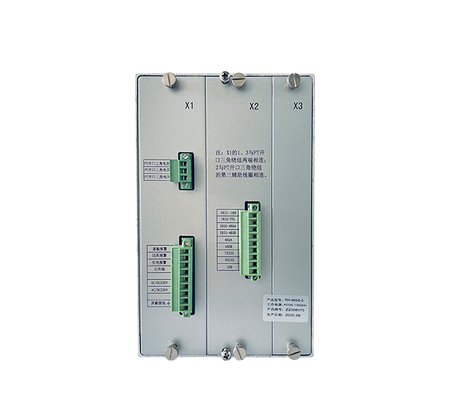
Terminal diagram and wiring diagram

Figure 8-1 RN-MGS microcomputer harmonic elimination device rear terminal diagram

Fig. 8-2 Connection diagram of RN-MGS microcomputer harmonic elimination device and P T open delta winding
Description:
1, 1 0 ~ 2 0 K V substation installation; Each section of the bus is equipped with one bus.
2. The layout of the rear panel of the chassis is shown in Fig. 8-1, where each terminal is represented as: 1, 2 and 3 of terminal X1 are respectively connected with three end lines C, B and A of the P T open delta winding (as shown in Fig. 8-2); Note: B is derived from the third auxiliary coil of P T opening delta winding, and is specially added for the need of harmonic elimination of this device. It can use the original idle wire core of P T secondary side cable. 9. 10 Access to power supply; 12 is the shielding docking point; 4, 5, 6 and 7 are alarm signal nodes, among which 4 and 5 nodes are normally open contacts, 6 nodes are normally closed nodes and 7 nodes are public nodes. Nodes 1, 2, 3 and 4 of X2 terminal are B code pair time nodes, and nodes 5, 6, 7, 8 and 9 are communication nodes.
9 installation
9.1 this device installed in the control room, but the cable resistance is not greater than 3 Ω.

RN-MGS Device Outline Dimension Drawing (Unit: mm)

RN-MGS Device Installation Openings Dimensions (Unit: mm)
十. Communication Protocol
10.1 Initialization mode
-
use query type communication mode, the programmable device address, default is 00 h; The host address is programmable and defaults to 00H.
-
eight data bits, one start bit, 1 stop bit, asynchronous, parity, half duplex.
-
baud rate: 300, 600, 1200, 2400, 4800, 9600 BPS, programmable.
-
serial port: RS232 / RS485
10.2 Wiring method
⑴ RS232 interface: the interface chip is MAX232
External lead: TXD input line device External terminal number (TXD) : 24
External terminal number of RXD output line device (RXD) : 23
GND ground device external terminal number (GND) : 25
⑵ RS485 interface: the interface chip is MAX485
External leads: R+ unit external terminal number (485A) ----26
R- Device external terminal number (485B) ----27
10.3 Communication protocol
10.3.1 CDT specification
|
1
|
2
|
3
|
4
|
5
|
6
|
|
EBH
|
90H
|
EBH
|
90H
|
EBH
|
90H
|
|
Synchronization head
|
|
1
|
2
|
3
|
4
|
5
|
6
|
|
71H
|
F4H
|
01H
|
Device address
|
Host address
|
CRC8
|
|
Control word
|
|
1
|
2
|
3
|
4
|
5
|
6
|
|
F0H
|
Status code
|
00H
|
00H
|
00H
|
CRC8
|
|
Information word
|
Note: 1. The device sends messages to the upper computer more than once every 5 seconds or so.
2.8 data bits, 1 start bit, 1 stop bit, no check bit.
3. Asynchronous half duplex, baud rate 1200 ~ 9600bps.
4. Status code: 00H means normal operation, 01H means zero sequence resonance; 10H means positive sequence resonance and 11H means overvoltage.
10.3.2 Modbus specification
1) The upper computer sends messages
|
1
|
2
|
3
|
4
|
5
|
6
|
7
|
8
|
|
Station number
|
01H
|
00H
|
00H
|
00H
|
01H
|
CRC high byte
|
CRC low byte
|
|
Device address
|
Function code
|
Starting address
|
Number of reads
|
CRC16 calibration
|
2)Lower computer response message
|
1
|
2
|
4
|
5
|
6
|
|
Station number
|
01H
|
XXH
|
CRC high byte
|
CRC low byte
|
|
Device address
|
Function code
|
Status code
|
CRC16 calibration
|
Note: 1. The device adopts Modbus protocol RTU mode and CRC16 calibration.
2.8 data bits, 1 start bit, 1 stop bit, no check bit.
3. Asynchronous half duplex, baud rate 1200 ~ 9600bps.
4. Status code: 00H means normal operation, 01H means zero sequence resonance; 10H means positive sequence resonance and 11H means overvoltage.
11 Service Guide
1) Service tenet
-
customer satisfaction, it is our duty!
-
continuous improvement, it is our duty.
2) After-sales matters
-
within one year from the date of purchase free maintenance;
-
failure a year later, according to the installation location and contract negotiation to solve;
-
just after the equipment installation and debugging, please fill out the feedback form equipment, and telephone, fax or mail it back to my company,

 Language