1. Introduction
The RN-PGY type relay protection test power supply panel is based on the Ministry of Energy’s "Power Plant, Substation Engineering and Relay Protection Test Instrument Configuration Norm", "Relay Protection Test Regulations" and the "Power System Relay Products designed and manufactured in accordance with the relevant provisions of "Key Points of Anti-accident Measures for Electrical Protection and Safety Automatic Devices". It provides a reliable, stable and convenient AC and DC test power supply for the field relay protection test work, and provides a reliable guarantee for improving the quality of the relay protection test work and ensuring the safety of personnel and equipment.
This equipment is suitable for power plants, substations and large and medium-sized industrial enterprises, and can be used as a standard relay protection test power supply.
2. Features of RN-PGY type relay protection test power screen
★ It adopts dual power supply, which can be switched manually and automatically. The use of contactors can switch with load to ensure the reliability of power supply.
★ The AC power supply adopts a large-capacity isolation transformer to isolate the system power supply from the test power supply, and install a shielding layer between the primary and the secondary to protect the test power supply from the transient process of the power grid and other harmonic interference. The transformer adopts △/Y0 connection mode, which greatly weakens the third harmonic and ensures the quality of power supply.
★ The DC power supply can continuously and smoothly adjust the voltage to meet the needs of different test items;
★ The control of the AC power supply adopts the DZ47-60 automatic switch, which has fast action, long life, and has the functions of short circuit and overload automatic tripping.
★ The output AC power supply is equipped with a leakage protection switch to ensure the safety of test personnel. The switch has the advantages of stable performance, high sensitivity, reliable action, etc., and has automatic tripping functions for short-circuit and overload.
★ GM32M DC circuit breaker is used for the DC circuit, which has fast action, long life, and has the functions of short circuit and overload automatic tripping.
★ There is a simulation diagram on the screen to make it easy for the operator to identify and avoid misoperation.
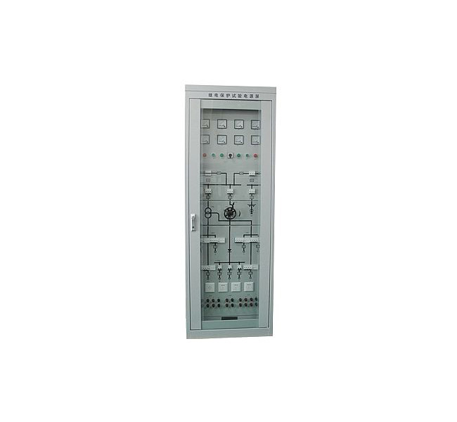
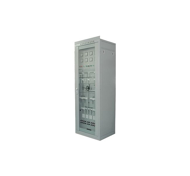
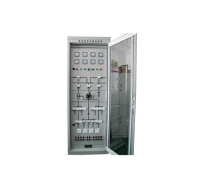
3. Product structure
a. RN-PGY type adopts PK-10 fully enclosed cabinet structure, front and rear doors with locks, and the screen body is made of plates.
b. The main internal components include isolation transformer, three-phase auto-voltage regulator, reactor, rectifier, capacitor, automatic air switch, leakage protection switch, ammeter, voltmeter and other components;
c. The instrument, indicator light and control switch are installed on the front panel, and the input and output wires can be connected through the terminal block and the terminal block.
4, use conditions
a. There should be measures to prevent rain and snow in the use place.
b. The altitude does not exceed 3000 meters.
c. Ambient air temperature: -15℃~+40℃.
d. The air humidity does not exceed 50% at 40°C, and higher relative humidity is allowed at lower temperatures, and does not exceed 90% at 20°C.
e. The mechanical vibration amplitude of the place of use is not more than 0.05mm, and the frequency is not more than 600 times/min.
f. The difference between the installation inclination and the plumb line is no more than 5°.
g. There is no danger of explosion in the surrounding medium, no conductive dust and corrosive gas.
5, electrical performance indicators
a. Insulation resistance: Under standard test atmospheric conditions, the insulation resistance between each circuit of the device and the housing is not less than 10MΩ; the insulation resistance between each independent circuit is not less than 10MΩ.
b. Dielectric strength: Under standard test atmospheric conditions, the above-mentioned circuits and independent circuits can withstand AC 50Hz, voltage 2kV (effective value), and the test lasts 1min without insulation breakdown or flashover.
c. Impulse voltage: Under standard test atmospheric conditions, each AC circuit and DC circuit should be able to withstand a short-time impulse test of a standard lightning wave of 5kV (peak).
d. The AC circuit uses DZ47-60 small automatic switch, the mechanical life is more than 20,000 times on and off, and the instantaneous breaking current can reach (4~7) Ie.
e. The DC circuit uses GM32M DC circuit breaker, and the instantaneous breaking current can reach (3~10) Ie (optional).
6. Main technical parameters
A. Communication section
a. Rated input voltage: three-phase 220V/380V, frequency 50Hz. ;
b. Rated output voltage: 220V/380V, three-phase four-wire, a total of three outputs;
58V/100V, three-phase four-wire, a total of three outputs.
c. When the three-phase input is balanced, the output unbalance is less than 1%.
d. The third harmonic component is less than 3%.
e. The input transformer capacity is 15kVA, and the maximum output current is 3×22.8A under the eight-hour working system.
B. DC part
a. The power input is AC three-phase 380V;
b. The output DC voltage is continuously adjustable from 0 to 250V, divided into three outputs;
c. The capacity of the rectifier transformer is 5kVA, and the maximum output current is 20A under the eight-hour working system;
d. Output DC ripple coefficient K<1.5%.
7, working principle
a. The power input adopts 220V/380V dual power supply, and the two power sources are not switched on at the same time, and the contactor is used to switch. The selector switch "SA" is placed in the manual, stop, and automatic positions, and the power can be switched between manual, stop and automatic.
b. The AC circuit obtains output voltages of 220V/380V and 58V/100V through the isolation transformer "1TM". The three parallel output 380V voltages are controlled by switches 6QF, 7QF, and 8QF respectively, and monitored by voltmeters 1PV, 2PV, and 3PV respectively. Uab, Ubc, Uac voltage; The 100V voltage of three parallel outputs is controlled by switches 9QF, 10QF, and 11QF, and the Uab, Ubc, and Uac line voltages are monitored by voltmeters 4PV, 5PV, and 6PV respectively;
c. The DC circuit is obtained by a three-phase auto-voltage regulator 1TC, a rectifier transformer 2TM, a three-phase bridge rectifier circuit and a filter circuit to obtain a continuously adjustable DC voltage of 0 ~ 250V, and is monitored by a DC ammeter 1PA and a voltmeter 7PV.
d. In order to facilitate the wiring during use, the AC output has three forms, namely the terminal button form in front of the screen, the terminal block form behind the screen and the multi-purpose power socket form. The AC output "Ⅰ", "Ⅱ" and "Ⅴ" and "Ⅵ" in the plane simulation diagram are respectively 220V/380V and 58V/100V front-screen terminal button output and "1D" rear-screen terminal block output; XS" is a multi-purpose power socket output. There are two types of DC output, "Ⅲ" and "Ⅳ" are output in the form of terminal buttons in front of the screen and output in the form of terminal block behind the screen "1D". The output form is selected according to the needs, and it is very flexible and convenient to use.
8. Installation instructions
a. Fix the screen body first, and connect the ground terminal button to the ground network reliably, and then introduce the three-phase AC power into the terminal block A1, B1, C1, N1 or A2, B2, C2, N2 behind the screen.
b. According to the screen simulation diagram, check all the control switches and changeover switches to make them in the off position, so that the voltage regulator is in the lowest output position, that is, turn it counterclockwise to the "0" position.
c. Put the switch "SA" in the stop position, close the AC power input switches 1QF and 2QF, and close the control switches 15QF and 16QF. At this time, the two power indicator lights 1HL1 and 2HL2 will light up; put SA in the manual position, Press 1SB, 1KM to pull in, and 1HL2 to light; press 2SB, 2KM to pull in, 1KM to turn on, and 2HL1 to light; put SA in the stop position, 1KM or 2KM to turn on. Put SA in the automatic position, 1KM or 2KM pulls in, 1HL2 or 2HL1 shines. Put the SA in the stop position and open the 1KM or 2KM. 1KM and 2KM have an electrical interlocking relationship, and only one contactor can be closed at the same time, so that one power supply is guaranteed.
d. When a contactor is closed, the transformer "1TM" is powered on, and the three-phase AC voltmeter has instructions. The 1PV, 2PV, and 3PV instructions should be 380V, and 4PV, 5PV, and 6PV indicate 100V.
e. Close the AC output leakage protection switches 6QF and 7QF respectively, then there are two sets of terminal buttons "Ⅰ" and "Ⅱ" in the front of the screen to output 220V/380V AC voltage; close 8QF, the terminals a1, b1, and c1 at the back of the screen , N1 has a 220V/380V AC voltage output.
f. Close the AC output leakage protection switches 9QF and 10QF respectively, then there are two sets of terminal buttons "Ⅴ" and "Ⅵ" in the front of the screen to output 58V/100V AC voltage; close 11QF, then terminals a2, b2, c2 on the back of the screen , N2 has a 58V/100V AC voltage output.
g. Close the 4QF AC switch, send power to the rectifier transformer, adjust the handle of the three-phase auto-voltage regulator, the DC voltmeter 7PV has an indication, which can be continuously adjusted from 0 to 250V; close the DC output switch 12QF, 13QF, then The buttons "Ⅲ" and "Ⅳ" on the front of the screen have DC voltage output; when 14QF is closed, the terminals "DC+, DC-" on the back of the screen have one output.
h. Close the AC socket switch 5QF, the socket has 220V/380V AC voltage output.
9, matters needing attention
a. This device has two input power sources, which cannot be closed at the same time; it can be operated with load.
b. When the DC output is disabled, the voltage regulator should be adjusted counterclockwise to the lowest output position.
c. The rated voltage of the leakage switch is 415V. The device is used for step-down on 58V/100V circuits (9QF, 10QF, 11QF). When the test button is pressed, it cannot be tripped because it cannot reach the simulated leakage current value, but in actual use, it can still protect the trip (not more than 30mA) when it encounters low resistance grounding.
10. Ordering instructions
a, PGY type screen body structure is PK-10 standard design, with additional sealing plates on both sides, please indicate the screen body size when ordering.
b. The company can design relay protection test power supply screens with different structures according to user requirements. Users should specify specific requirements (or provide drawings) when ordering.
c. The company can design power screens with different performances on behalf of users (or customize them according to drawings provided by users).
d. The screen size, color, order quantity, etc. should be indicated when ordering.
e. The configuration in the manual is subject to change without notice, and the drawings and data provided with the goods shall prevail.
f. This equipment is a maintenance-free product. Three guarantees within one year, long-term technical support.

 Language