1 General overview
Ensuring the safety of electric power production is the most important work content of electric power enterprises, and this work is undertaken by a special electric power safety supervision department. An important responsibility of power safety supervision and management is to strengthen the management of power safety tools and equipment to ensure the safety, inventory management, and use supervision of tools and equipment, especially in relation to the "two tickets" (ie work tickets and operation tickets). Used in conjunction to standardize power production safety measures, improve power production safety guarantees, and establish corresponding safety precautions and preventive measures for this purpose.
At present, power safety supervision and management is mainly based on manual management, supplemented by preliminary computer information management, mainly including "two votes", "two measures" and other content, but lacks real-time monitoring of safety tools and instruments, and the "two votes" "Supporting monitoring and management methods, therefore, it is impossible to discover potential safety hazards in power production in time. The power safety monitoring and management based on manual supervision and post-event summary can no longer meet the requirements of prevention and real-time monitoring in power safety monitoring and management in modern enterprises. Requirements.
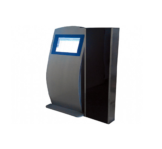
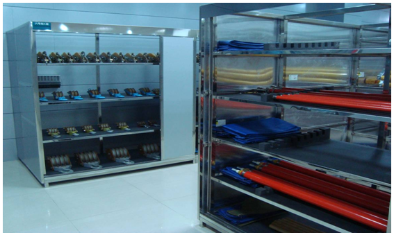
The system uses the most cutting-edge technology, RFID radio frequency identification technology combined with intelligent temperature and humidity control, to achieve intelligent management of the warehouse. The system can realize unmanned tool room management, support automatic identification of tools and equipment and personnel entry and exit, the system automatically records the RFID information of the person responsible for the acquisition of tools and equipment, and can display real-time information about the acquisition of tools and equipment in the library and related information of the responsible person when it is started It can also remind the person responsible for the test date to expire the test.
To this end, with the Safety Supervision Department as the center, the establishment of a networked chemical equipment monitoring and management system covering branches, power supply stations, and substations to the users will surely improve the safety supervision of electric power companies from the aspects of digitization, electronics, and networking. Management level.
2 System architecture
The system mainly includes two parts: hardware part and application software.
3 System hardware
The hardware part of the safety equipment monitoring and management system includes the following components:
3.1 System hardware structure diagram
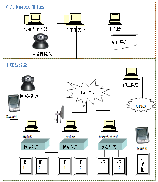
3.1.1 System hardware composition
Database server Application server Central management station Status collector RFID radio frequency identification Status detection sensor
Label printer, handheld PDA smart terminal, label paper, access controller, tool cabinet access lock, access card reader:
Access Control RFID Card Industrial Grade SMS Module Heating Machine Temperature and Humidity Sensor Dehumidifier Camera
3.1.2 Tools and equipment monitoring methods
There are many ways to classify the safety tools and instruments of power supply companies, such as: according to the type, physical location, and status of the tools and instruments. In order to better combine the actual work needs of users and further explain our technical solutions, we will distinguish the tools and appliances by the physical location of the tools and appliances, and use different monitoring methods for the tools and appliances stored in different locations. In order to monitor tools and equipment more clearly and reasonably. According to the storage location, tools and equipment are mainly divided into: tools and equipment stored in the tool and equipment cabinet (referred to as the tool in the cabinet), stored on the tool rack, including video surveillance, personnel access, and indoor environment detection (referred to as indoor Appliances), tools and tools used or to be used by the construction team (referred to as tools outside the cabinet).
Monitoring method of tools and appliances in the cabinet:
1. Tools and equipment that have a greater impact on production safety:
We use real-time monitoring for this kind of tools, and we will introduce this method in detail in the following introduction.
2. Appliances that have less impact on production safety:
This type of tool has a relatively small impact on safe production. In order to save costs, we use barcodes on the tools (barcodes are the unique asset numbers of the tools), and collect data through a handheld smart terminal. The same as the cabinet we will introduce below The monitoring of external equipment is consistent. For details, please refer to the introduction of monitoring equipment outside the cabinet.
Monitoring method of tools and instruments in the warehouse:
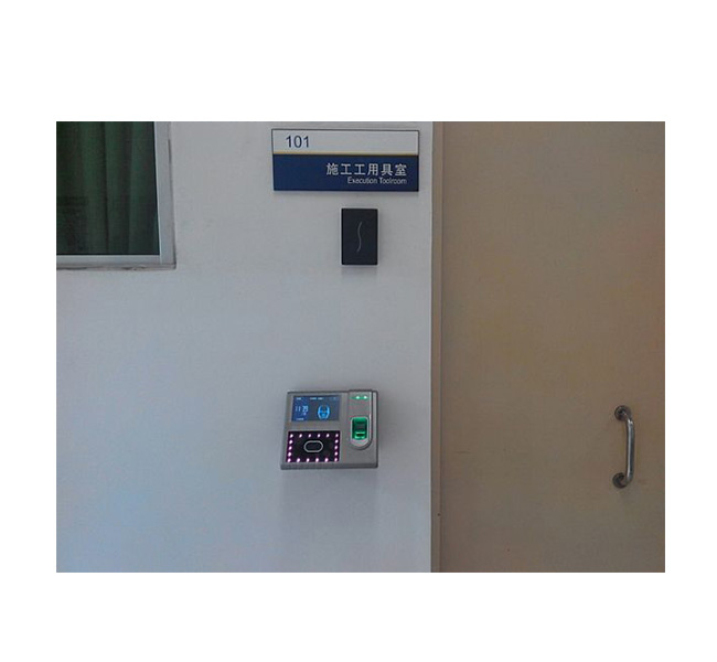
Record the entry and exit status of all personnel and the entry and exit status of equipment through a combination of cameras and access control systems. Stored on the safety tool rack, the equipment can be monitored in the form of RFID tags.
Indoor environment, through the intelligent environment to identify temperature, humidity, etc., fixed values can be set freely or manually controlled. Taking the fixed value as an example, when the indoor environment exceeds the fixed value range, the system will automatically start dehumidification and heating equipment according to the situation. Ensure that the warehouse works in a permitted environment.
Monitoring method of equipment outside the cabinet:

In addition to the online GRPS monitoring, the on-site operation monitoring method also supports the offline method. The handheld smart terminal uses the latest tool library downloaded when online as a standard for testing.
The operation process is as follows:
1. Use a bar code printer to print bar codes, each bar code has a unique number to ensure the uniqueness of tools and instruments in the system;
2. The barcode has been affixed on the tools and tools before the construction team leads the tools;
3. The inspector uses a handheld smart terminal to scan the information on the barcode, and upload the read information to the database via GPRS. GPRS is the abbreviation of "General Packet Radio Service" (translated as "General Packet Radio Service"). It is a set of wireless transmission methods developed by the concept of "Packet Switching". The so-called "packet exchange" is to encapsulate data into many independent packets, and then send these packets out one by one. The form is somewhat similar to sending parcels in a post office. See below:

4. The database feeds back the information required by the tools and equipment to the handheld smart terminal, thus realizing the monitoring and management of the tools and appliances, for example: when the returned tool and equipment information is unqualified, the inspector will deal with it in time to ensure the monitoring and management of the safety tools and equipment , To ensure the safety of power construction.
5. When a handheld PDA terminal is used for on-site monitoring operations, the labels of the tools and instruments are scanned through GPRS to obtain the information of the currently used work ticket and the number of the tools used. The safety supervisor can compare with the actual work ticket to judge the on-site operation Whether the tools and equipment are currently legal work tickets, providing more in-depth monitoring of the use of tools and equipment.
3.2 System application software
3.2.1 Application software system structure
The safety equipment monitoring and management system is built on the internal local area network of the power supply company. The entire system is based on the J2EE architecture, adopts the B/A/S three-tier structure model, and applies new technologies such as AJAX. It makes up for the shortcomings of the B/A/S model, balances the load of the application server and the client, and greatly improves the user experience of front-end and back-end information interaction operations and multi-category business data applications.
The whole system consists of three parts: the client of the safety tool and equipment monitoring management system, the communication monitoring platform, and the database server. The software architecture is shown in the figure below:
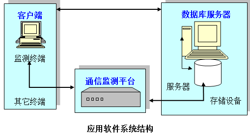
The communication monitoring platform includes a communication module and a short message module. The communication module is responsible for sending and receiving and data storage. The information collected by the smart terminal is sent to the database, and the database feeds back the corresponding data to the smart terminal. The client is the customer's monitoring and management of the entire tool and equipment, file query, business processing, statistical analysis, system management and other functions.
The database server includes basic information database and graphic data files.
3.2.2 Application software permission structure
Based on years of information system development experience and power industry software development experience, the company has designed and developed a scientific, controllable and rigorous authority management structure. This structure can solve the authority problem of most information systems.
The system authority structure is provided as a platform function, and the system provides a general authority management mechanism, which has nothing to do with any business. The control level of system authority management function is divided into three levels:
Function menu authority level
If the system operator passes the uniform application program, passes the operator identity authentication, the system displays the main interface of the system according to the function menu operation granted by the operator. Only the function menu that the operator has the right to use is displayed on the main interface of the system. Unauthorized functions are transparent to the operator.
Functional component layer
For the functions granted to the operator, the system provides further authorization: the operator is granted access to certain buttons and components on the page, and unauthorized buttons are transparent to the operator.
Data domain control layer
For the function pages that the operator can open, we control the data domains that the operator can access. Only authorized data domains can be modified by the operator. Unauthorized data domains can only be viewed and cannot be modified by the operator.
Authority management of system data area
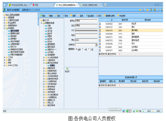
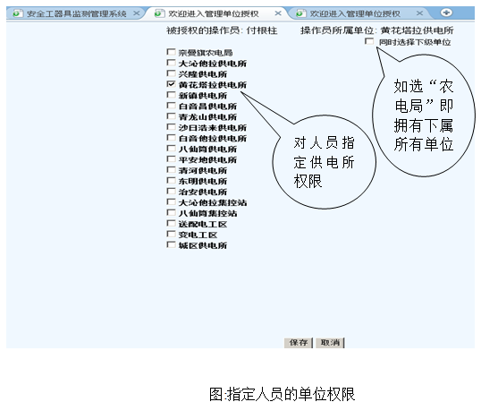
The authority management of the system data area means that the operator can only operate the data in his own jurisdiction, and the data in other areas is transparent to the operator.
The system achieves the purpose of data area authority management through the authorization of the management unit. When the operator logs in, he will retrieve the list of management units that he can handle according to his identity. All functions with management area conditions provide the operator with his own authority The range of management unit selection makes it impossible for him to manipulate data beyond the scope of his authority.
For example: the relevant personnel of the branch can only view the information of the branch, while the head office can view the relevant information of each branch.
3.2.3 Application software functional structure
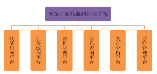
The system application software part adopts the DFC system structure accumulated by our company's long-term engagement in the integrated development of electric power information applications, and carries out software design with platform-based thinking, and builds the following application software platforms:
1. Function integration platform
2. Business process platform
3. Data dictionary platform
4. Information query platform
5. Statistical analysis platform
6. System management platform
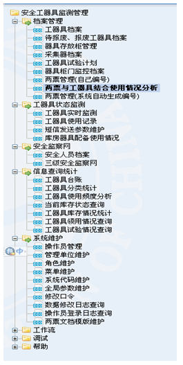
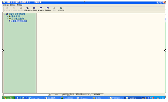
System function structure diagram
Application software functions are closely combined with application requirements, and object-oriented application software system analysis and design methods are adopted to realize the following application functions, as shown in the following figure:
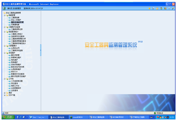
3.2.4 File management
3.2.4.1 Tool file management
Establish electronic files of safety tools and appliances, implement unique numbers for global safety tools and appliances, manage technical files of safety tools and appliances in different categories, determine the management department, storage cabinet number, and location in the cabinet, and visualize the status of the tool and appliance files.
According to the global safety network, a safety personnel file is established so that it can be associated with the relevant "two tickets" and the person responsible for the management of tools and equipment during application.
3.2.4.2 Security personnel management
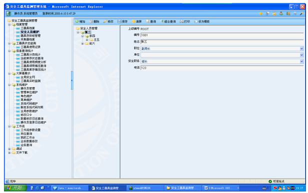
Establish files for the storage cabinets of safety tools and equipment of each management unit, realize a globally unified unique number, and specify and explain the layout of each cabinet and the form of storage equipment in detail. For graphical storage management and monitoring.

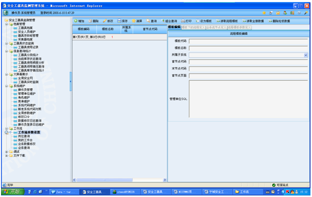
3.2.5 "Two votes" tool and appliance template management
According to the requirements of "two tickets" management, interface with the data of the two tickets system, according to the "two tickets" template to establish the corresponding tool and appliance type template. When two tickets are issued, the corresponding list of types and quantities of tools and instruments that should be used can be generated in the system at the same time, so as to check and monitor corresponding to actual work.

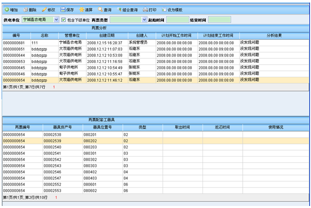
3.2.6 Analysis of the combined use of "two votes" and tools
Combining the data of the two tickets and the usage of the appliances collected through this system, compare and analyze whether the safety tools and appliances are accurately carried in the process of the two tickets, and give the analysis results.
3.2.7 "Two Tickets" and Security Management of Access Control
According to the data interface with the two-ticket system, combined with the authority of the operator and guardian provided by the two-ticket system, the tool cabinet access control judgment is performed. The networked access card reader reads the card number information and sends the card number to the safety tool system. The basic card number is associated with the operator or guardian's tool cabinet authority to check the two votes and open the door.
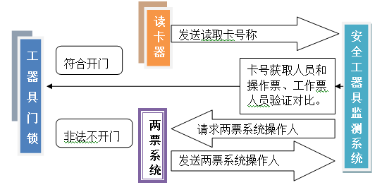
It can be equipped with a switch for emergency opening of the door by the highest authority management personnel or using a super user card. The cardholder has the highest authority to open the door in an emergency. All door opening records are available in the system for detailed information, including opening time, Information such as door opener, cabinet number, work ticket number, etc. The security personnel have detailed files in the system, the access control RFID card number, and the personnel's security tools and equipment cabinet door permissions are registered in the detailed files, including their units, substations or power supply stations. The operator in the two-ticket system can correspond to the security tool and equipment system personnel. When the access control card is read and obtained, the card is reported to the networked tool and equipment system. The system combines the two-ticket system and its specified operating time range to make judgments and send unlock signals. Automatically open the corresponding tool cabinet door.
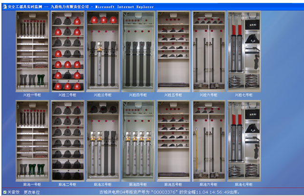
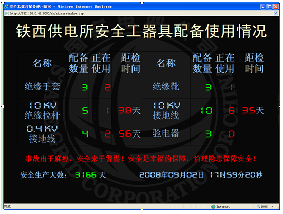
3.2.8 State monitoring of tools and instruments
Through the LAN, the monitoring center monitors the in-position status of various safety tools and instruments online 24 hours a day. When the status of the tools and appliances changes, it is automatically recorded in the database, the current status is automatically updated, and the status is displayed graphically on the large screen. If it is non-working time or set time, the status change can also be sent to the mobile phone of the manager through the SMS platform.
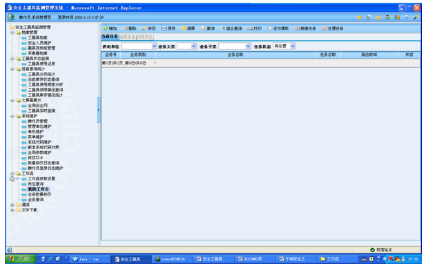
Real-time monitoring interface: 24-hour online monitoring of the in-position status of various tools and appliances. When the status of tools and appliances changes, it will be automatically recorded in the database, the current status will be automatically updated, and prompts will be given in graphical and voice alarm modes at the set time Inside, the status change can be sent to the mobile phone of the manager through the SMS platform. Combine with the "two votes" to analyze whether tools and equipment are properly equipped during construction
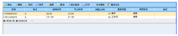
Maintenance of SMS sending parameters:
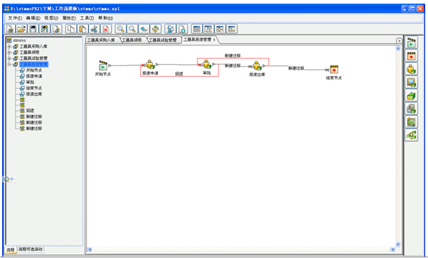
3.2.9 Business Process Management
Use the business processing platform to manage related business processes in the management of safety tools and equipment. If the relevant business flow
2014011620540948948.png
Workflow parameter setting: realize parameterized management, which is easy to maintain; if the process has and used in the MIS system, you can use the existing process of MIS, and if there is not in MIS, use the business process of this system. The design of the business process uses workflow middleware to embed our system, including the following functional menus:
Position query: query which processes in a certain position are active;
My workbench: display the current operator's pending work list and provide processing entry;
Business query: query various information about the process that has been taken. Business data modification: provide modification entry for part of the process data;
Part of the business process is as follows:
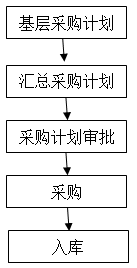
3.2.9.1 Purchase and storage of tools and instruments
The management of safety tools and instruments should start with the procurement plan. According to the configuration, use and inventory of the overall safety tools and equipment in the previous year, the user shall apply for the summary and formulate the annual procurement plan. After the procurement plan is reported to the bureau’s budget for approval (may be adjusted), enter the procurement process according to the approved plan (independent procurement, bidding procurement or outsourcing procurement, etc., the process is not managed in this system). After the procurement is completed, the safety supervision department of the bureau will follow the regulations Warehousing. The business process is as follows:
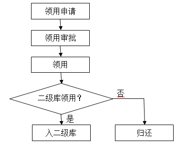
3.2.9.2 Requisition of tools and instruments
Safety tools and instruments are managed in the secondary library, that is, all tools and instruments are purchased in the central library after unified purchase, and the power supply stations and other users will collect them from the central library according to the application or plan. The use stage is stored in the secondary library of each unit. The used tools and instruments are returned to the general warehouse through the process of testing and scrapping, and the temporary borrowing between the secondary warehouses is temporarily not included in the management process.
The secondary library also adapts to this process for engineering or personal tools and equipment.
The business process of obtaining safety equipment is as follows:

3.2.9.3 "Two tickets" tools and instruments supporting management instructions: if they are used by projects or individuals, they do not need to be placed in the secondary warehouse, but they need to be returned.
Obtain the "two votes" worksheet from the MIS system, and generate a list of tools and instruments based on the related "two votes" types and templates, which will be modified by the ticket maker as the corresponding list of tools and instruments for the corresponding "two votes", and the system will automatically check Whether the tools and instruments in the inventory meet the requirements.
The corresponding business process is as follows:
After the list is generated, when the "two tickets" are executed, the monitoring system automatically detects whether the relevant tools and instruments are taken according to the list, the system automatically records and prompts the monitoring center.
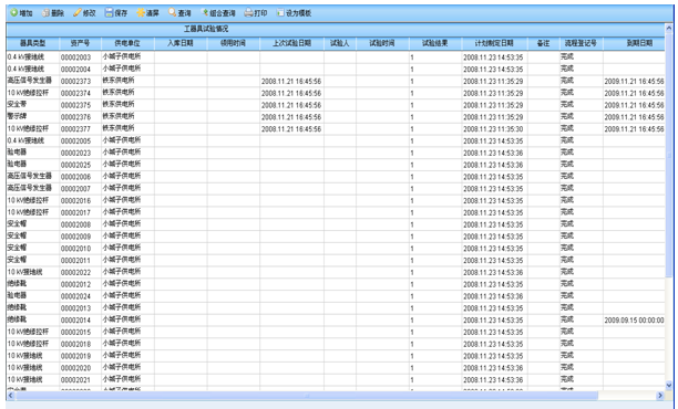
3.2.9.4 Tool and appliance test management
According to the latest test date, test period and other information in the safety robot file, compile the test and inspection plan of the safety tool and implement, and complete the inspection and test management.

3.2.9.5 After the end-of-life management test and inspection of tools and instruments are completed, they shall be directly put into the central warehouse, and then used by the user; according to requirements, the management unit may not be changed during the test process, and the user shall receive it back after the test is completed.
For tools that fail the test or are damaged in use, they will be scrapped at the end of the year or on a regular basis. The scrapped tools and tools will be removed from the inventory, and the asset management department will be responsible for their follow-up processing, not managed in this system.
The management process of scrapping of safety tools is as follows:
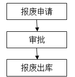
Note: The scrapping out of the warehouse is executed according to the approved list.
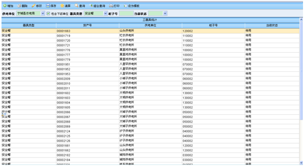
3.2.10 Query Statistics
Query and make statistics on safety tools and equipment and their status, and provide managers with timely, comprehensive and in-depth power safety tools and equipment query, statistics, analysis and management.
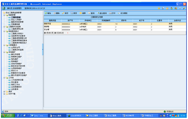
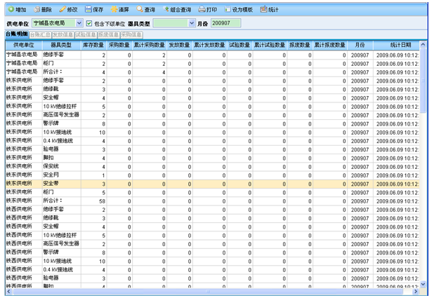
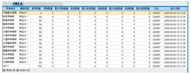
3.2.10.1 Tools and equipment ledger
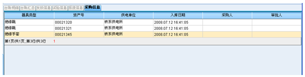
The tool and equipment ledger is divided into a general ledger and a detailed ledger. The general ledger can count the classified total information of the construction period equipment of different units in different months. The information mainly includes the unit, category, inventory quantity, purchase quantity, cumulative purchase quantity, and issued quantity , Cumulative issued quantity, scrapped quantity, accumulated scrapped quantity, test quantity, cumulative test quantity, month, statistical date, etc.; the detailed ledger can separately display the details of the current month's purchase, issuance, scrap, and test under the condition of the associated general ledger .
General ledger and its summary information:
Detailed ledger (purchase details):
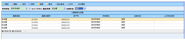
In addition to the automatic status change report (display, voice, text message (non-working hours)) of the monitoring center, the system provides the current inventory status of safety tools and instruments. 3.2.10.2 Current inventory status query
The current status of safety tools and equipment can be inquired by unit and category, and the latest state change time can be understood, and the status of tools and equipment can be understood in time.
3.2.10.3 Classification statistics of tools and instruments
Classified statistics of current tools and instruments according to conditions such as unit, status and current status. The statistics can be used as a departmental tool and equipment management ledger.
3.2.10.4 Inquiry about the use of tools and instruments
It is possible to inquire about the use of tools and instruments in any time period, and analyze the difference in combination with changes in status.
You can query the use of tools and equipment in any period of time by department and type.

3.2.10.5 Statistics on inventory of tools and instruments
Count the inventory of various tools and instruments or the overall situation.

3.2.10.6 Frequency analysis of tools and appliances, etc.
According to the records of changes in the in-position status of tools and equipment, statistical analysis of the frequency of use of safety tools and appliances, so as to evaluate the efficiency of the use of safety tools and appliances.

3.2.10.7 Statistics of tool and appliance test
The detailed test conditions of tools and instruments can be counted by time and time.
3.2.10.8 Work ticket statistics
Through the interface with the two-vote system, it can work with the "two-vote" system to count the number of two votes, the pass rate and the list of unqualified votes for each department and team by year and month, as well as statistics on each person's issuance and approval The number of operation tickets, work tickets, and the number of qualified and unqualified tickets.
Statistics of the two-vote pass rate of the department: count the number of qualified work votes, unqualified work votes, qualified operation votes, unqualified work votes, pass rate and the number of work votes, unqualified work votes, and qualified operation votes of each department within the specified time range. Number of unqualified work votes and pass rate
Statistics of the two-vote pass rate of the team: Count the number of work votes, unqualified work votes, qualified operation votes, unqualified work votes, and pass rate of each shift in the specified time range
List of unqualified tickets: display unqualified work tickets and operation tickets within the specified time range
Individual operation ticket statistics: count the number of operation tickets operated by each person as the operator, guardian, person in charge of duty, and duty chief, the total number of operation ticket items operated and the operation qualification rate
4 Supporting software and middleware
Supported by this system are short message service platform, tool condition monitoring service system and workflow middleware.
4.1 SMS Service Platform
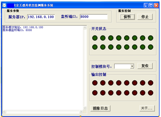
4.2 Tools and equipment condition monitoring service system
Responsible for communicating with the state controller, real-time monitoring and control of the state controller.
4.3 Workflow middleware
Using workflow middleware: middleware includes process designer and engine, which can realize dynamic workflow design and control.
The typical process designer interface is as follows:
5 Local monitoring of power supply station
This system mainly emphasizes the centralized monitoring and management functions of the safety supervision department. It also provides corresponding solutions for the monitoring and display of local tools and equipment in the power supply station and power supply station: LED screens and voice prompt function modules controlled by the status collector. The module is selected according to user needs.
The module can be selected in combination or separately (that is, the LED screen and the voice prompt for opening the cabinet door are separately optional). The LED screen is responsible for dynamically displaying the status of tools and equipment in the second and third level tools and equipment rooms of the power supply station, and the specific display content can be customized. The voice prompt module can prompt the corresponding safe operation when the cabinet door of the tool is opened.
5.1 PC local display and prompt
In addition to the above special LED screen and voice controller, a PC can also be used to realize local display and prompt functions. The interface form is as follows:
Description: The equipment and usage status of tools can be displayed separately according to management unit (global, station or station). If the PC is equipped with multimedia (sound card, speaker), it can also give voice prompts when the cabinet door is opened and closed and the status of tools and equipment changes.
5.2 SMS monitoring service
Safety personnel in power supply stations and global inspection personnel can monitor the use of safety tools and instruments through SMS services, and send them to the mobile phones of designated personnel according to the specified scope of authority. The sending time can be set and the sending template format can be customized;
For example: XXXX year XX month XX day XXX took out the helmet number XXX in cabinet X; XXXX year XX month XX day XXX returned the helmet number XXX in cabinet X;
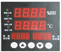
5.3 Environmental display
5.4 Video surveillance display
Thank you for reading this plan, and welcome to our company for inspection and visit, and provide valuable opinions. I hope that this system plan will help you better in your management!

 Language