1 scope of application
This series of voltage switching devices can be used for voltage switching of two bus sections.
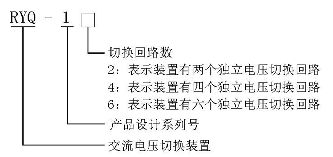
2 Model definition
3 Technical conditions
3.1 Environmental reference conditions
Environment temperature: 20±2℃
Relative humidity: 45%~75%
Atmospheric pressure: 86~106Kpa
3.2 Normal use conditions
Ambient temperature: -10℃~+50℃
Relative humidity of environment: not more than 90%
Atmospheric pressure: 80~110Kpa
Limit temperature during storage and transportation: -25℃~+70℃
3.3 Rated parameters
Rated voltage of DC power supply: 220V, 110V;
Allowable voltage fluctuation range: 0.8 to 1.15 times the rated voltage.
3.4 Maximum power consumption:
DC circuit: no more than 6W in the case of rated voltage 220VDC.
3.5 Maximum capacity of contacts:
Cut-off load capacity: DC 250V or less, τ=5ms, inductive load 50W, resistive load 150W;
AC below 250V, load 1200VA;
Allow long-term connection current: 5A.
3.6 Insulation resistance: The insulation resistance between the exposed non-charged metal parts connected together with the conductive terminals of the measuring device with an open circuit voltage of 500V megohmmeter should not be less than 10MΩ.
3.7 Insulation withstand voltage: each terminal can withstand a power frequency voltage of 2000V to the chassis shell, and the same group of contacts can withstand a power frequency voltage of 1000V, and there is no breakdown in one minute.
3.8 Anti-interference performance: Comply with the national GB6162-85 "Electrical interference test of static relays and protection devices" standard.
3.9 Electrical life: In the DC250V circuit, cut off the current τ=5ms, 50W, more than 104 times.
3.10 Mechanical life: The contact is 3 million times in no-load state.
4 Device working principle and layout
4.1 The schematic diagram of the voltage switching device is as follows:
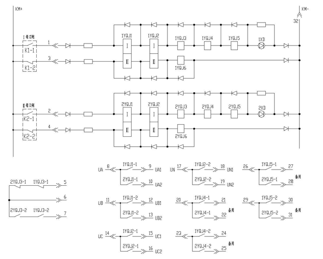
4.2 Working principle:
There are two options for starting the AC voltage switching circuit of the switching device. The first method is that the two-stage bus switching is started by the respective isolation switch open contact and the closed contact is reset. The second method is that the two-stage bus switching is started by the isolation switch open contact , Reset each other.
4.2.1 Mode 1 (both busbar switching is initiated by the open contact of the respective isolation switch, and the closed contact is reset) Action process:
When the auxiliary opening contact K1-1 of the Ⅰ female isolation switch is closed, 1YQJ1~1YQJ6 will act, and the contacts of 1YQJ1 and 1YQJ2 are self-maintaining, and 1XD is on, indicating that the AC voltage is connected by the Ⅰ female PT; when the Ⅰ female isolation switch is auxiliary open When contact K1-1 is opened and auxiliary closed contact K1-2 is closed, 1YQJ1 and 1YQJ2 are reset. The contacts of 1YQJ3~1YQJ6 are instantaneous contacts without self-holding.
When the auxiliary opening contact K2-1 of the Ⅱ female isolation switch is closed, 2YQJ1~2YQJ6 will act, and the contacts of 2YQJ1 and 2YQJ2 are self-maintaining, and 2XD is on, indicating that the AC voltage is connected to the Ⅱ female PT; when the Ⅱ female isolation switch is auxiliary open When contact K2-1 is opened and auxiliary closed contact K2-2 is closed, 2YQJ1 and 2YQJ2 are reset. The contacts of 2YQJ3~2YQJ6 are instantaneous contacts without self-holding.
4.2.2 Mode 2 (both busbar switching of the two sections are started by the open contact of the isolated knife switch, mutual reset) action process:
First, short-circuit the terminals "1" and "4", "2" and "3" on the back panel of the device. When the auxiliary opening contact K1-1 of the Ⅰ female isolation switch is closed, 1YQJ1~1YQJ6 will act, of which 1YQJ1, 1YQJ2 The contact is self-maintaining, 1XD is on, indicating that the AC voltage is connected by the Ⅰ female PT, and 2YQJ1 and 2YQJ2 are reset at the same time. When the auxiliary opening contact K2-1 of the Ⅱ female isolation switch is closed, 2YQJ1~2YQJ6 will act, among which the contacts of 2YQJ1 and 2YQJ2 are self-maintaining, and 2XD is on, indicating that the AC voltage is connected by the Ⅱ female PT and resetting 1YQJ1 and 1YQJ2. When the auxiliary opening contacts of the I and II bus isolation switch are closed, for the self-holding relay, the first closed bus circuit relay is in the operating state, and the self-holding relay of the subsequent excitation circuit does not operate.
4.3 Device backplane terminal diagram (a terminal diagram of an independent switching circuit)
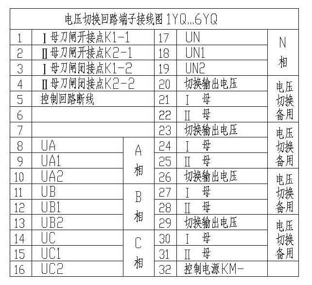
4.3.1 In mode 1 (both busbar switching is initiated by the respective isolation switch open contacts and closed contacts reset), terminals "5" and "6" are the control circuit disconnection signal output contacts, if simultaneous action signals need to be output , Should be terminals "18" and "19".
4.3.2 In the second mode (both busbar switching is initiated by the isolation switch open contact, mutual reset), terminals "5" and "6", "6" and "7" are control circuit disconnection and switching respectively Simultaneously actuate the signal output contact.
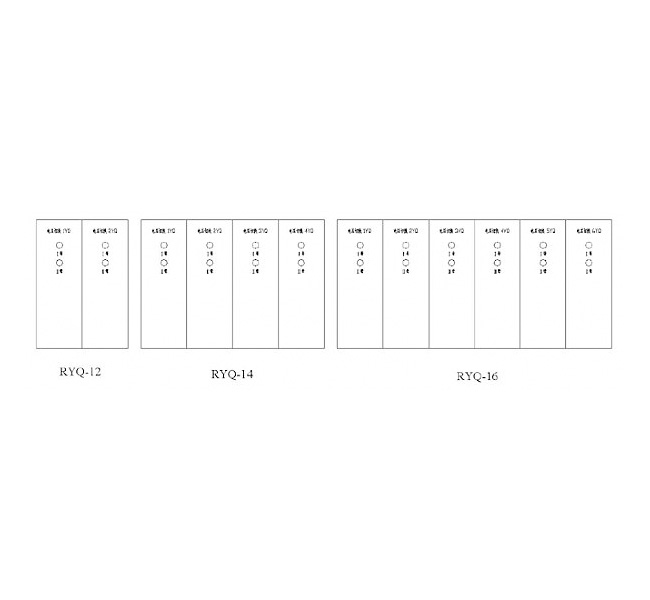
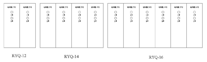
4.4 Device panel layout drawing
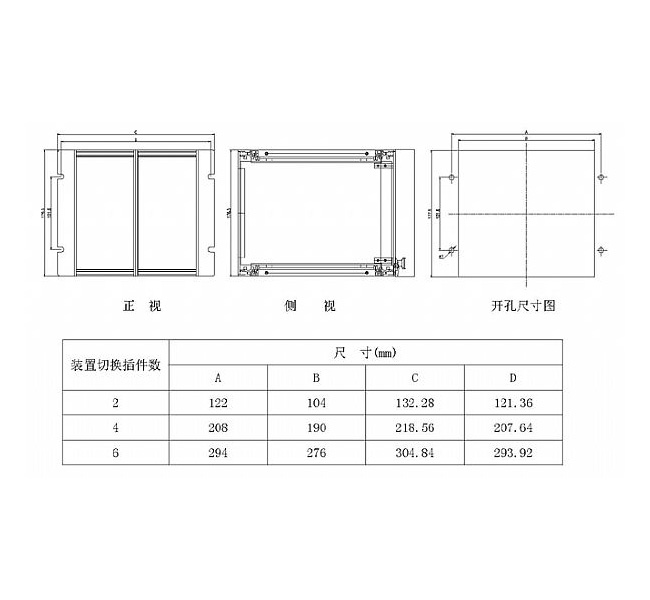
5 Device shape and hole size structure diagram
Using a standard 4U chassis, two switching plug-ins form a unit chassis.

6 Ordering instructions
Please specify the device model, specification, quantity, DC power supply rated voltage and other requirements when ordering.

 Language