1 Application range
This series of relays are used in electric motors and feeder units of power plants and power equipment, as a protection for judging overload and grounding short circuit in the power system loop. After a certain delay, the outlet cuts off the fault loop and sends an alarm signal.
2 Model definition
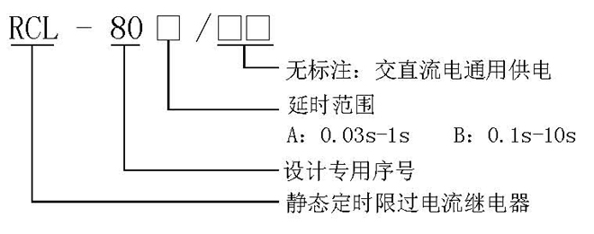
3 Working principle and main performance
3.1 Working principle
The AC current is converted by the AC converter to the AC voltage required by the relay; then the harmonics other than 50HZ are filtered through the 150HZ band-stop filter and the 50HZ band pass; then the DC voltage is converted into the setting circuit through rectification and filtering; the setting circuit The setting value is changed by changing the magnification of the operational amplifier; the output voltage UZ of the setting loop is sent to the level detector and compared with the comparison voltage UB; and then the time loop is started by the drive and the time loop is activated. Start the signal loop at all times and send an alarm.
3.2 Main performance
3.2.1 This relay is mainly composed of integrated circuits. Stable performance, high reliability, high accuracy of the action value, small discrete value, wide setting range, fast action and return speed, good return coefficient, small load on the transformer, vibration resistance, anti-interference and high insulation level.
3.2.2 The protection setting value is set by the dial switch on the relay panel, the setting is intuitive and convenient, the debugging is simple and convenient, and there is no need to adjust on site.
3.2.3 The relay has operation, action and signal indicator lights.
4 Technical conditions
4.1 Environmental reference conditions
Environment temperature: 20±2℃
Relative humidity: 45%~75%
Atmospheric pressure: 86~106Kpa
4.2 Normal use conditions
Ambient temperature: -10℃~+50℃
Relative humidity of environment: not more than 90%
Atmospheric pressure: 80~110KPa
Limit temperature during storage and transportation: -25℃~+70℃
The altitude of the place of use: no more than 2500 meters
The surrounding medium in the use environment has no explosion hazard; it does not contain corrosive gas; the concentration of conductive dust contained should not reduce the insulation level below the allowable limit value.
Reliable power supply.
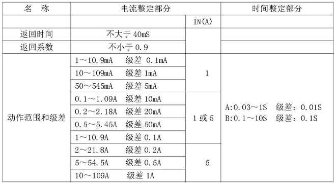
4.3 Characteristic parameters
4.3.1 The rated parameters are as follows:
4.3.2 Auxiliary power supply: 220V 110V AC and DC universal
Allowable fluctuation range of auxiliary power supply voltage: 0.8~1.15 times of rated voltage
4.4 Maximum power consumption:
AC current loop: each phase is not more than 0.5VA at 5A; each phase is not more than 0.2VA at 1A.
Auxiliary power supply: not more than 6W at 220V
4.5 Maximum capacity of contacts:
When the voltage is not greater than 250V, the signal alarm contact capacity is 5A
Delay outlet contact capacity is 2A;
4.6 AC circuit overload capacity:
AC current loop: continuous work under 2 times the rated current;
It can work for 10S under 10 times of rated current;
It can work for 1S under 40 times the rated current.
4.7 Insulation resistance: Use an open-circuit voltage 500V megger to measure the insulation resistance between the exposed non-charged metal parts or shells of the relays connected to each conductive terminal and should not be less than 10MΩ.
4.8 Insulation withstand voltage: each lead-out terminal to the housing locking screw can withstand a power frequency voltage of 2000V, and the same group of contacts can withstand a power frequency voltage of 1000V, which lasts for one minute without breakdown.
4.9 Anti-interference performance: Comply with the national GB6162-85 "Electrical Interference Test of Static Relays and Protection Devices" standard.
4.10 Electrical life: In the DC250V circuit, cut off the current τ=5ms, 50W, more than 104 times.
4.11 Mechanical life: The contact is 3 million times in no-load state.
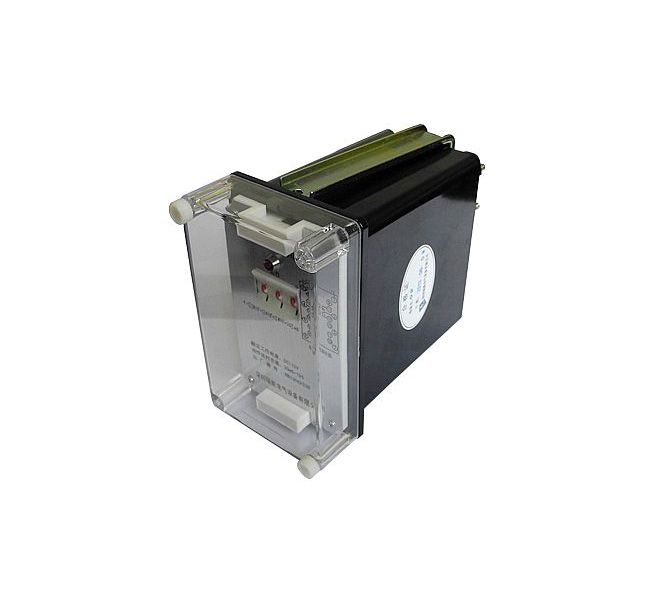
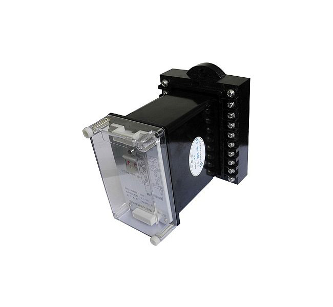
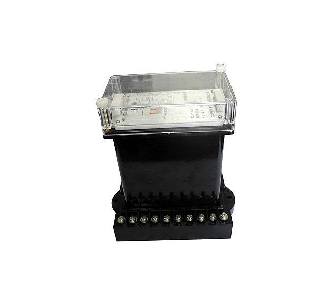
5 Structure type (see the relay structure size diagram for details)
5.1 The rear wiring structure of the embedded board AK11, AP11 and the rear-view wiring diagram of the protruding board front wiring AQ11 (subject to the company's product samples)
6 Use
6.1 Before energizing the relay, confirm whether the voltage level and current value of the connected relay are consistent with the actual parameters, otherwise the relay may be damaged; check whether the relay is damaged during transportation and storage, and the relay screw fasteners should not be loose; There are damaged parts, please contact us to replace them.
6.2 Use the dial switch to set according to the formula on the relay panel.
* Current partial setting formula: I=K[□+0.1□+1]A
K value depends on the setting range: if the setting range is 1~10.9A, K=1 I=[□+0.1□+1]A
When the setting range is 5~54.5A, K=5 I=5[□+0.1□+1]A
When the delay time setting range is 0.03~1S, t=[0.1□+0.01□+0.03]S
When the delay time setting range is 0.1~10S, t=[□+0.1□+0.1]S
7 Ordering instructions
Please specify the relay model, specification, quantity, auxiliary power supply rated voltage, AC rated current, setting range, structure and other requirements when ordering.

 Language