1 Application range
This series of time relays are used as delay components for relay protection in power plants, substations and power systems. It is also suitable for other industrial fields that require precise delay control. It is especially suitable for old electromagnetic time relays (A relay, Xu Ji) was updated to solve the urgent contradiction that the electromagnetic time relay is used in the relay protection of the power system, which causes the difficulty of matching the protection time difference.
2 Model definition

3 Working principle and main characteristics
This series of time relays are composed of integrated logic circuits. Use the counter to reach the delay, use the dial switch to set the time
This series of time relays has a wide range of time delay, high accuracy, small difference, convenient setting, high reliability, and strong anti-interference performance. The export relay adopts a fully sealed high-quality relay (dust-proof, moisture-proof, and anti-breaking), which can operate for a long time. Features of low power consumption.
4 Technical conditions
4.1 Environmental reference conditions
Environment temperature: 20±2℃
Relative humidity: 45%~75%
Atmospheric pressure: 86~106Kpa
4.2 Normal use conditions
Ambient temperature: -10℃~+50℃
Relative humidity of environment: not more than 90%
Atmospheric pressure: 86~110KPa
Limit temperature during storage and transportation: -25℃~+70℃
The altitude of the place of use: no more than 2500 meters
The surrounding medium of the use environment has no explosion hazard; it does not contain corrosive gas; the concentration of conductive dust contained should not reduce the insulation level below the allowable limit value.
Reliable power supply.
4.3 Characteristic parameters
Relay return time: less than 20mS
4.4 Auxiliary power supply rated voltage: 220VDC; 110VDC; 48VDC; 380VAC; 220VAC, the allowable voltage fluctuation range is 0.8 to 1.15 times the rated voltage.
4.5 Maximum power consumption: when 220VDC, the single delay is not more than 6W; the double delay is not more than 9W.
At 220VAC, the single delay is not more than 12VA; the double delay is not more than 15 VA.
4.6 Maximum capacity of contacts:
Cut-off load capacity: DC 250V or less, τ=5ms, inductive load 50W, resistive load 150W;
AC below 250V, load 1200VA;
Allow long-term connection current: 5A.
4.7 Insulation resistance: Use an open-circuit voltage 500V megger to measure the insulation resistance between the exposed non-charged metal parts or shells of the relays connected to each conductive terminal and should not be less than 10MΩ.
4.8 Insulation withstand voltage: each lead-out terminal to the housing locking screw can withstand a power frequency voltage of 2000V, and the same group of contacts can withstand a power frequency voltage of 1000V, without breakdown in one minute.
4.9 Anti-interference performance: Comply with the national GB6162-85 "Electrical Interference Test of Static Relays and Protection Devices" standard.
4.10 Electrical life: In the DC250V circuit, cut off the current τ=5ms, 50W, more than 104 times.
4.11 Mechanical life: The contact is 3 million times in no-load state.
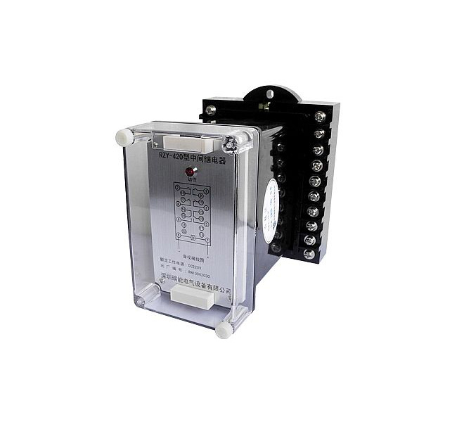
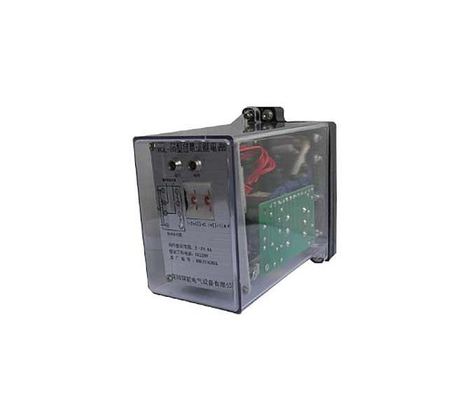
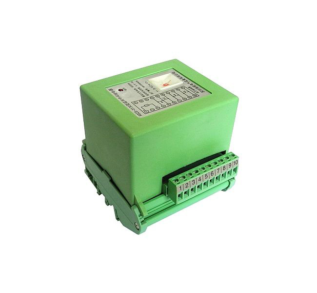
5 Structure type (see the relay structure size diagram for details)
5.1 Embedded board rear wiring structure AK11, AP11 and protruding board front wiring AQ11 rear view wiring diagram (subject to company product samples)
5.2 JK-1/18 structure rear view wiring diagram (subject to company product samples)
5.3 DZ-1 structure terminal block type terminal wiring diagram (subject to company product samples)
6 Use
6.1 Before energizing the relay, confirm whether the voltage level of the connected relay is consistent with the actual parameters, otherwise the relay may be damaged; check whether the relay is damaged during transportation and storage, and the relay screw fasteners should not be loose; if there are damaged parts , Please contact us to replace it for you.
6.2 The relay is triggered by an external contact to start timing, and the contact should have no serious jitter.
6.3 The relay does not need to be adjusted, and only needs to be checked regularly.
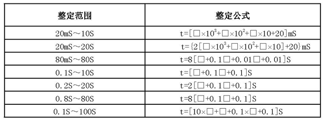
6.4 Use the dial switch to set the time according to the formula on the relay panel.
7 Ordering instructions
Please indicate the relay model, rated voltage of the power supply, structure, quantity and other requirements when ordering. If a time relay contact is used to directly trip, be sure to inform and provide the trip current value. Otherwise, the relay contact will be broken directly and damaged.

 Language