1 Application range
This series of intermediate relays are used in various protection and automatic control devices to increase the number and capacity of the protection and control loop contacts.
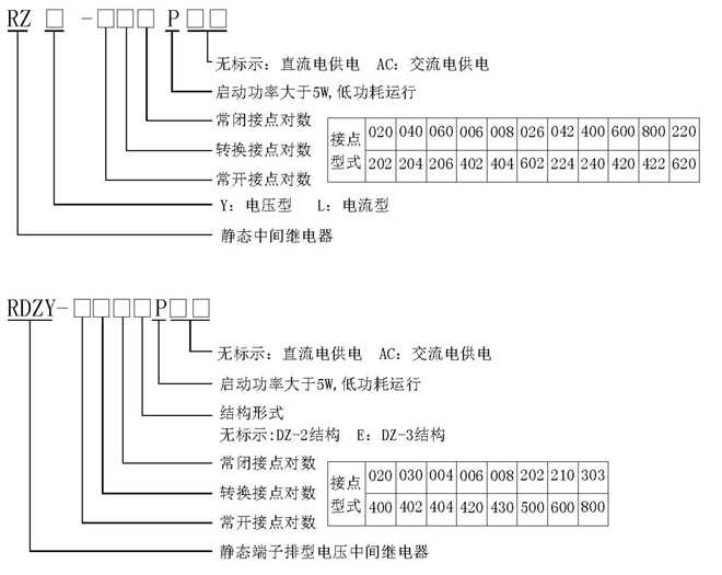
2 Model definition
3 Main performance
This series of intermediate relays uses electronic control loops to control multiple fully sealed relays to be turned on or off at the same time. And has the following performance and characteristics:
3.1 Adopt high-performance sealed relay, moisture-proof, dust-proof, uninterrupted wire, high reliability.
3.2 The principle of integrated circuit is used to overcome the difficulty of contact adjustment of electromagnetic relays and the problem of low delay accuracy. It has good vibration resistance and reduces maintenance workload and labor intensity to a certain extent.
3.3 There will be indicator lights after the relay is activated.
3.4 The electrical and mechanical life of the relay is long.
3.5 High insulation withstand voltage level, large contact capacity and low contact resistance.
4 Technical conditions
4.1 Environmental reference conditions
Environment temperature: 20±2℃
Relative humidity: 45%~75%
Atmospheric pressure: 86~106KPa
4.2 Normal use conditions
Ambient temperature: -10℃~+50℃
Relative humidity of environment: not more than 90%
Atmospheric pressure: 80~110KPa
Limit temperature during storage and transportation: -25℃~+70
The altitude of the place of use: no more than 2500 meters
The surrounding medium of the use environment has no explosion hazard; it does not contain corrosive gas; the concentration of conductive dust contained should not reduce the insulation level below the allowable limit value.
4.3 Characteristic parameters
4.3.1 Rated voltage: 24VDC, 48VDC, 110VDC, 220VDC, 22OVAC, 380VAC; allowable voltage fluctuation range: 0.8 to 1.15 times the rated voltage.
4.3.2 Action value
DC voltage type: about not more than 70% of the rated voltage, about not less than 50% of the rated voltage.
AC voltage type: about not more than 70% of the rated voltage, about not less than 30% of the rated voltage.
DC current type: not more than 70% of rated current, not less than 30% of rated current.
4.3.3 Return value: not less than 5% of the rated value.
4.3.4 Action and return time: not more than 20mS.
4.3.5 Action time of high-power start relay: no more than 30ms, return time no more than 20ms.
4.4 Maximum capacity of contacts:
Cut-off load capacity: DC 250V or less, τ=5ms, inductive load 50W, resistive load 150W;
AC below 250V, load 1200VA;
Allow long-term connection current: 5A.
4.5 Maximum power consumption
DC voltage type: under 220VDC, no more than 3W.
AC voltage type: under 220VAC, not more than 3VA.
High-power start intermediate relay: greater than 5W.
4.6 Insulation resistance: Use an open-circuit voltage 500V megger to measure the insulation resistance between the exposed non-charged metal parts or shells of the relays connected to each conductive terminal and should not be less than 10MΩ.
4.7 Insulation withstand voltage: each lead-out terminal to the housing locking screw can withstand a power frequency voltage of 2000V, and the same group of contacts can withstand a power frequency voltage of 1000V, which lasts for one minute without breakdown.
4.8 Anti-interference performance: Comply with the national GB6162-85 "Electrical interference test of static relays and protection devices" standard.
4.9 Electrical life: In the DC250V circuit, cut off the current τ=5ms, 50W, more than 104 times.
4.10 Mechanical life: The contact is 3 million times in no-load state.
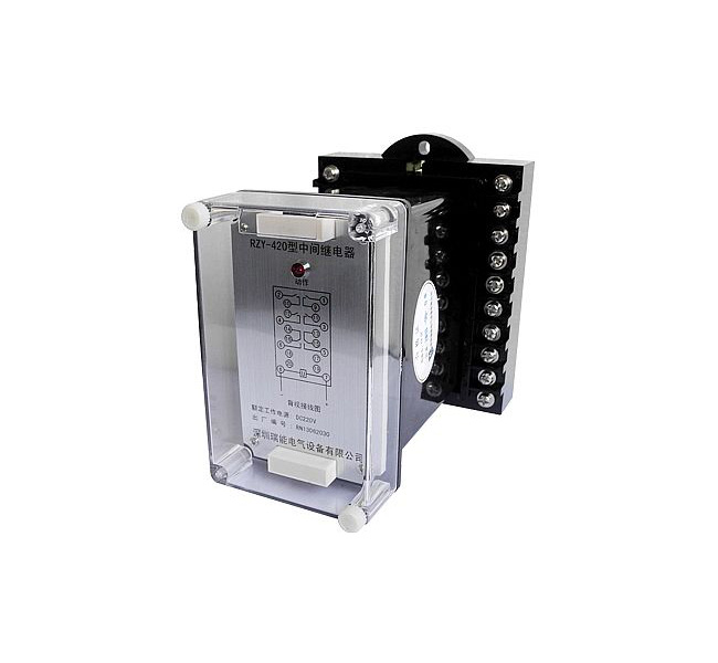
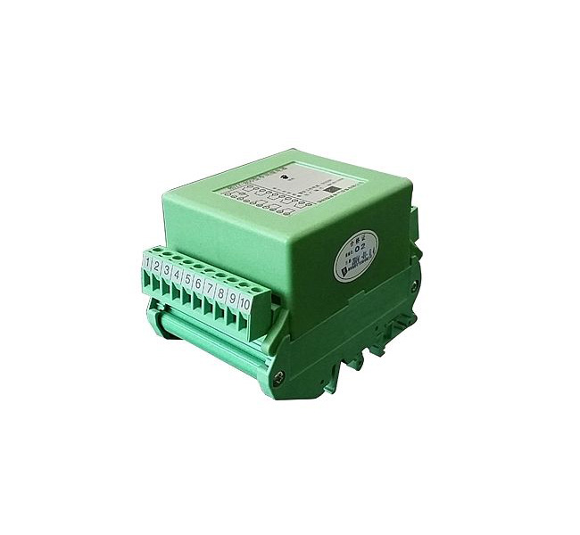
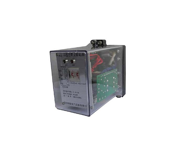
5 Structure type (see the relay structure size diagram for details)
5.1 Embedded board rear wiring structure AK11, AP11 and protruding board front wiring AQ11 rear view wiring diagram (subject to company product samples)
5.2 JK-1/18 structure rear view wiring diagram (subject to company product samples)
5.3 DZ-2 structure terminal block type terminal wiring diagram (subject to company product samples)
Terminal wiring diagram of special contact type relay (subject to company product samples)
5.4 DZ-3 structure terminal block type terminal wiring diagram (subject to company product samples)
6 Use
Before energizing the relay, confirm whether the voltage level of the connected relay is consistent with the actual parameters, otherwise the relay may be damaged; check whether the relay is damaged during transportation and storage, and the relay screw fasteners should not be loose; if there are damaged parts, Please contact us to replace it for you.
7 Ordering instructions
When ordering, please indicate the type, specification, quantity, structure, rated voltage or current and other requirements of the relay.

 Language